Adding Blinkers to an Onyx RCR
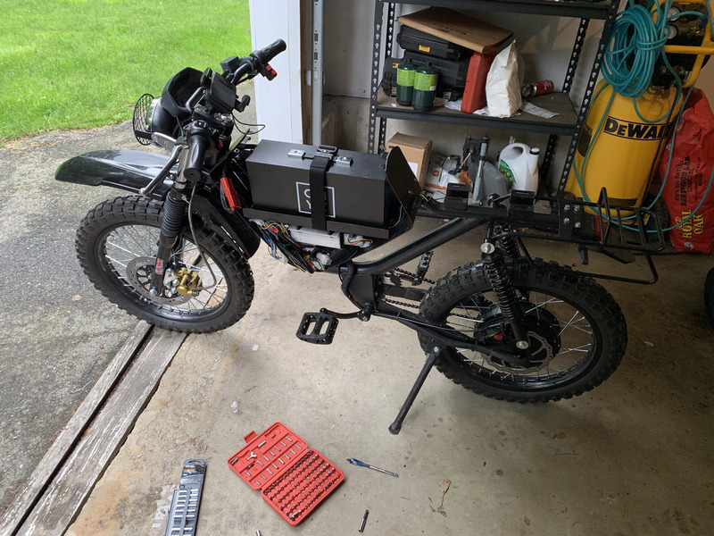
Last year I backed Onyx Motorbikes on Indiegogo, and last week I received my Onyx RCR. It’s incredible!
It doesn’t come with blinkers, but it does have a switch and the requisite wiring pre-installed. However, the blinker connector on the wiring harness does not conform to Onyx’s schematic, so it can be tricky to get all the wiring right if you’re a novice at electrical work or just don’t have much experience with a multimeter.
This post lays out instructions for what I believe is the easiest way to get blinkers working on the Onyx RCR. It does not require any relay, soldering, or permanent modification of the bike. It does not assume the reader has any background in electronics, and it does not discuss what is happening from a technical standpoint. This guide is the electrical equivalent of paint-by-numbers.
But first, receipts:
Materials
To complete this project, you will need the following components:
- Front and back 12V LED turn signals that accept constant current
- Mounting bracket for front turn signals
- 2.8mm 6-pin male automotive connector
- (3) 5-port Lever Nuts
- 6’ 22g yellow wire
- 6’ 22g blue wire
- 1’ 22g green wire
- 1’ 22g white wire
- 5.5’ 22g black wire
- 22g #10 spade crimp connector
- (4) 22g 1/4” female crimp connector
- (2) 5A ATC-type automotive fuses
You will also need the following tools:
- wire crimping tool
- wire cutters
- (2) pliers
- 3mm allen wrench
- socket wrench
- 10mm drive deep socket
- 4” or greater extension bar
Shopping List
Everything you need to complete this install is below. I offer this for referential purposes; you probably already have some of this stuff, or can find odds and ends in smaller quantities.
- Justech Universal Flowing Waterproof Motorbike LED Turn Signal ($14.95)
- 2 pcs/pair Motorbike Turn Signal Mount Bracket, Black ($5.57)
- Swpeet 700Pcs Automotive Electrical Wire Connectors Kit, 2.8mm 2 3 4 6 9 Pin ($16.63)
- 222-412 (20) 222-413 (20) 222-415 (20) Lever Nuts, 60 Pack Assortment ($16.99)
- Hook up Wire Kit (Solid Wire Kit) 22 Guage, 6 Colors ($15.99)
- Neiko 50413A Terminals and Connectors with 3-in-1 Tool ($12.59)
- Stalwart 75-HT3004 Utility Slip Joint Plier Set ($17.16)
- Bussmann ATC 5 Amp Fast-Acting Automotive Blade Fuses (5-Pack) ($3.97)
- Bondhus 10946 Set of 6 Balldriver L-wrenches, sizes 1.5-5mm ($5.92)
- Egofine 1/4 Inch Ratchet Set with 4-13mm and Extension Bar ($14.99)
Instructions
Remove the battery.
Turn off your battery, physically disconnect its red connector, turn on your dash display to drain any stored currents, and then turn it off. No matter what you see in the pictures that follow, leave your battery disconnected until you are all done.
Install the Blinkers
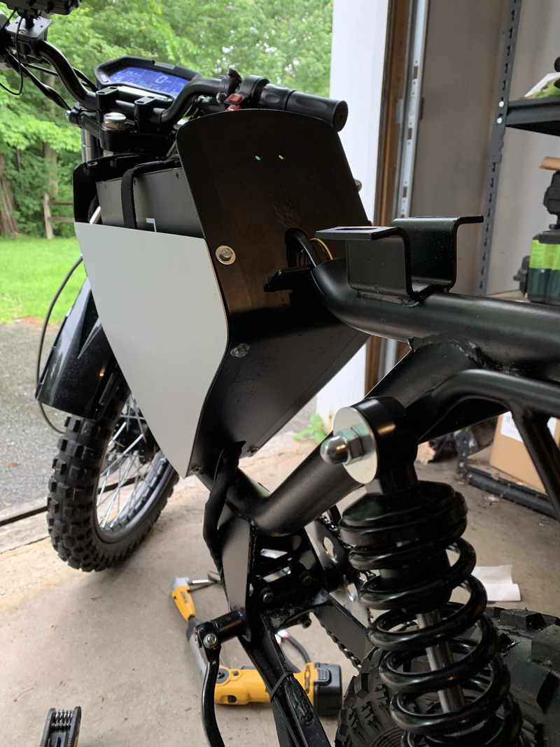
Put the mounts on the front fork, thread the blinkers through, and bolt them on:

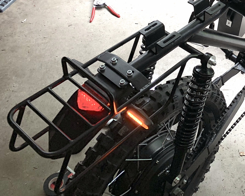
There are two holes in the side of the rear fender, near the brake light. Thread blinkers through them, and bolt them on just as you did in the front:
Build the Harness
The harness consists of four distinctly colored wires, each 1’ in length:
- Yellow. Connects to +12v input of right-signal LED on dash display. Strip far end and leave 1/4” bare wire.
- Blue. Connects to +12v input of left-signal LED on dash display. Strip far end and leave 1/4” bare wire.
- Green. Receives +12v when right blinker is active. Crimp far end to a 22g 1/4” female connector.
- White. Receives +12v when left blinker is active. Crimp far end to a 22g 1/4” female connector.
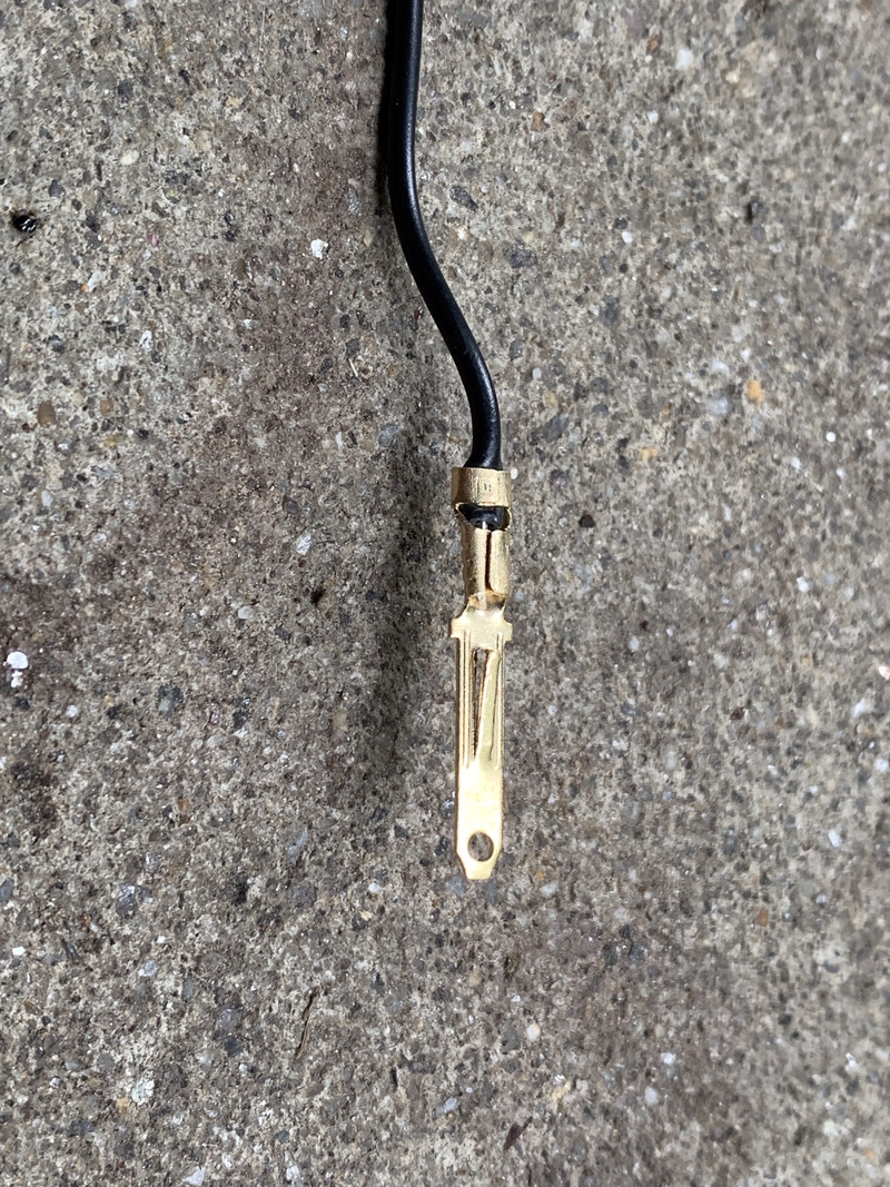
You are building the male side of the harness. When you crimp a connector plug to a wire, it should look like this:
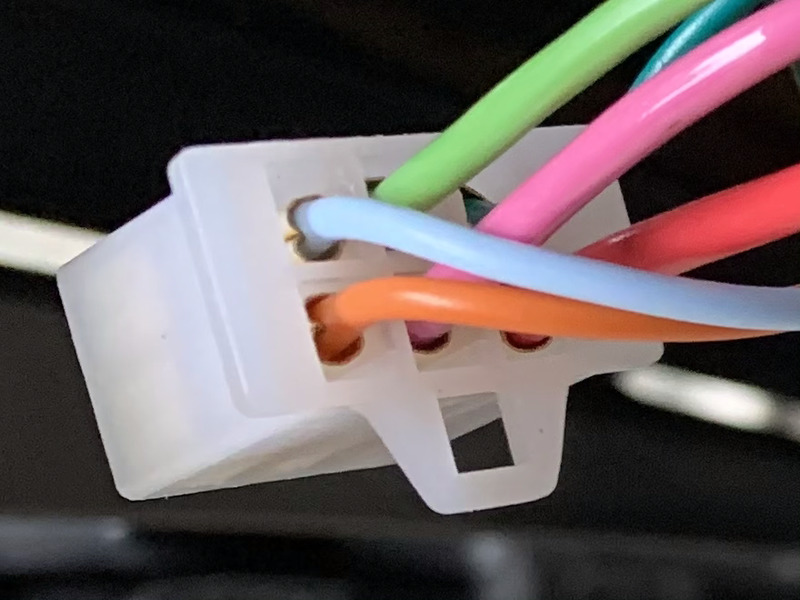
After crimping the four connections for the harness, insert the connectors into the connector. When you are looking at the side of the connector with the wires, and the latch is on the top, the top row will be blue-white-blank and the bottom row will be yellow-green-blank (see warning below photo before assembling):
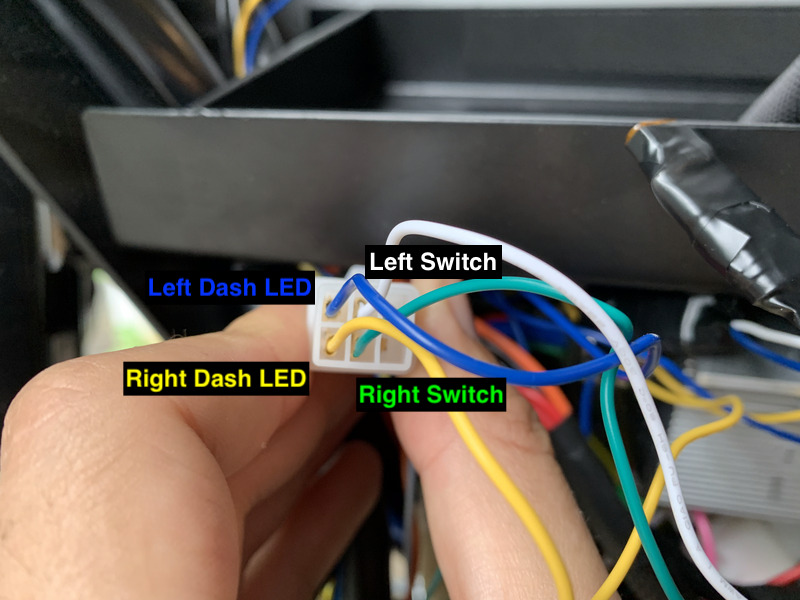
Warning: In mid-July 2019, Onyx began shipping a new wiring harness. It no longer matches the color or pinout in these instructions. If you have the new harness (yellow/pink/red/thin green/thick green wires on the signal port), you need to line up the wires on your plug so that they connect to the harness wires according to the following table:
| Old bike harness | New bike harness | Your plug |
|---|---|---|
| Blue | Thin green | Yellow |
| Orange | Yellow | Blue |
| Green | Thick green | Green |
| Pink | Pink | White |
Install the Harness
Remove the seat with a 10mm deep socket. A 4” socket extension bar is very helpful for this step.
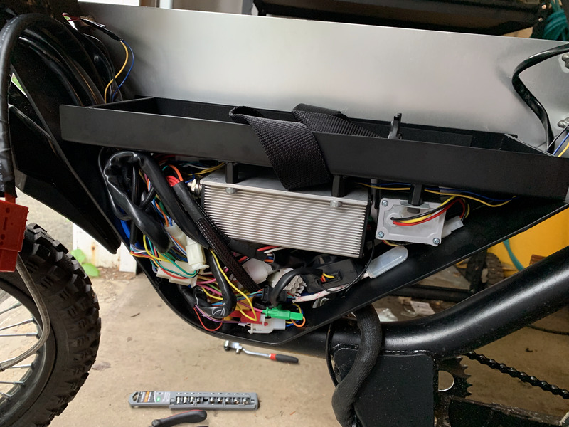
Take off the left aluminum side by removing the five tapered screws with a 3mm allen wrench. You now have this:
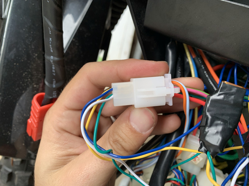
Insert that male connector that you built into the factory-provided female connector that looks like this:
When you connect the plug, it should look like this:
Be sure to build the harness as specified above. Do not rely on the official schematic – the pinout provided, as of Rev A, is incorrect.
Acquire a Ground Connection
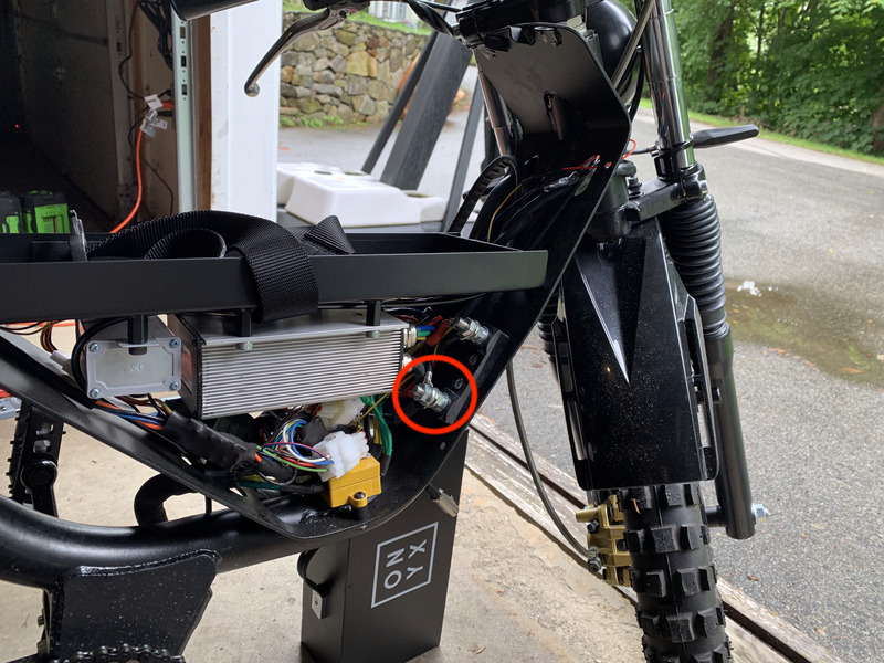
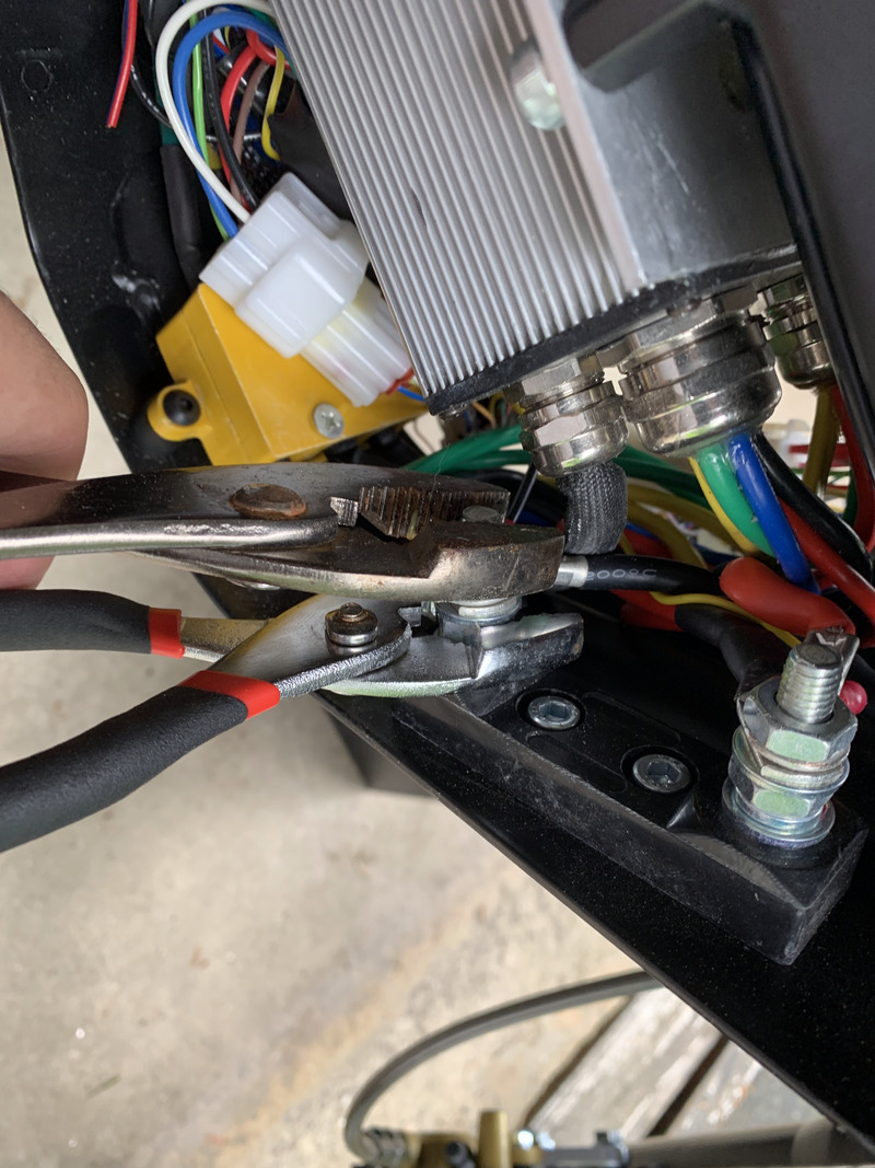
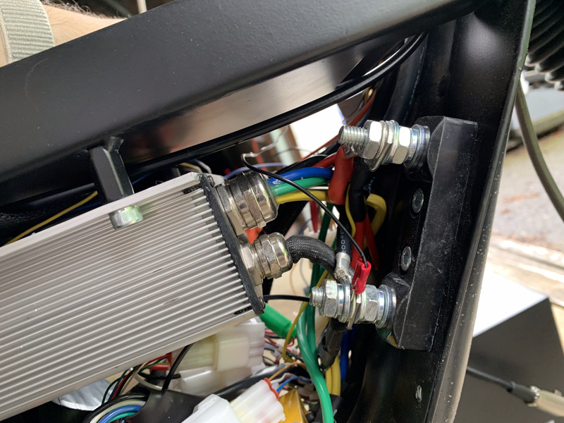
Remove the right aluminum side, just as you did the left. The ground lug that you need to access is toward the front of the bike on the bottom of the mounted plastic piece:
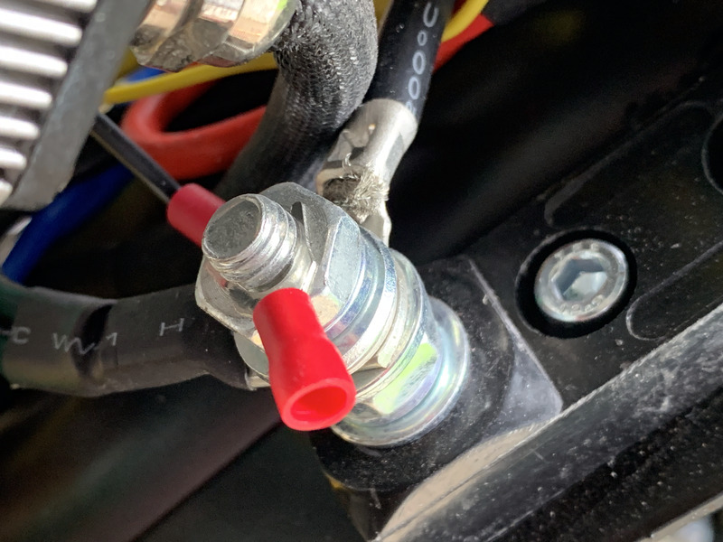
Crimp a 22gauge #10 spade terminal to a 1’ piece of black wire. Using a pliers, stretch the spade terminal so that it can go all the way around the ground screw:
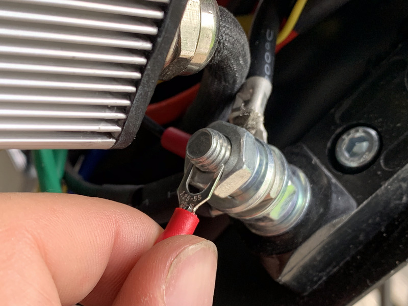
Using one pliers to hold the bottom hex bolt, and another to loosen the top one, create just enough space to insert your spade terminal into the ground connection array. Tighten the hex bolts when you’re done.
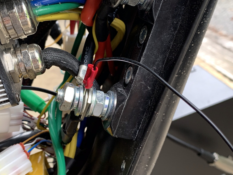
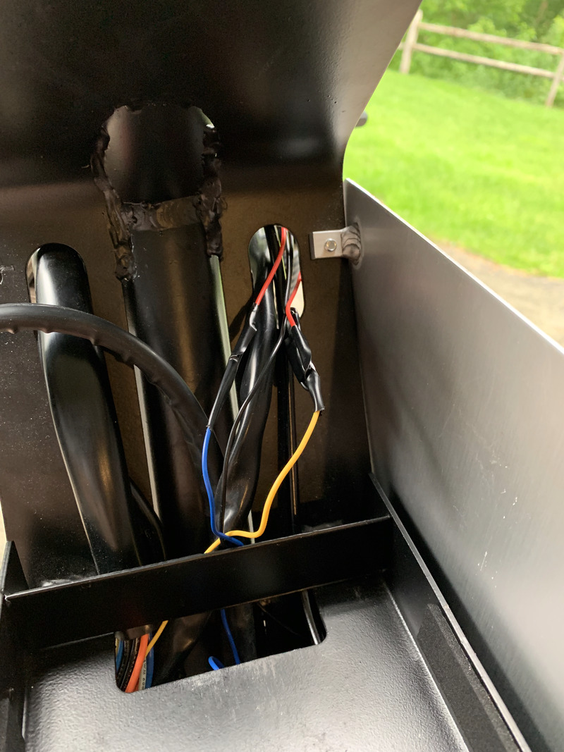
Feed your ground wire to the left side of the bike above the loose cabling, but below the enclosed wires:
Build the Fuse Assemblies
Cut a 1’ piece of blue wire. Strip one end, and crimp the other end to a 22g 1/4” female connector.
Take one of your 5A fuses, and connect the blue wire you just made to it using the female connector on the wire. On the other side of the fuse, connect the white wire from the harness you made.
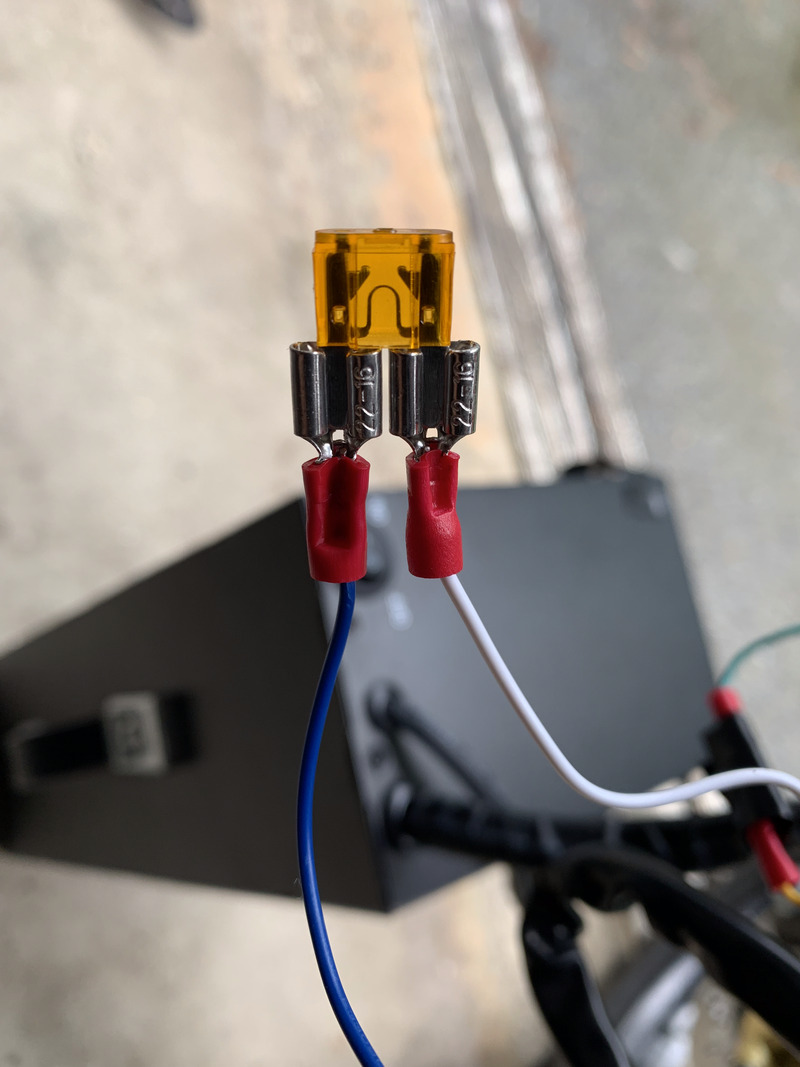
Using electrical tape, carefully insulate the two connections so they can never touch, and seal any exposed area around thee wires.
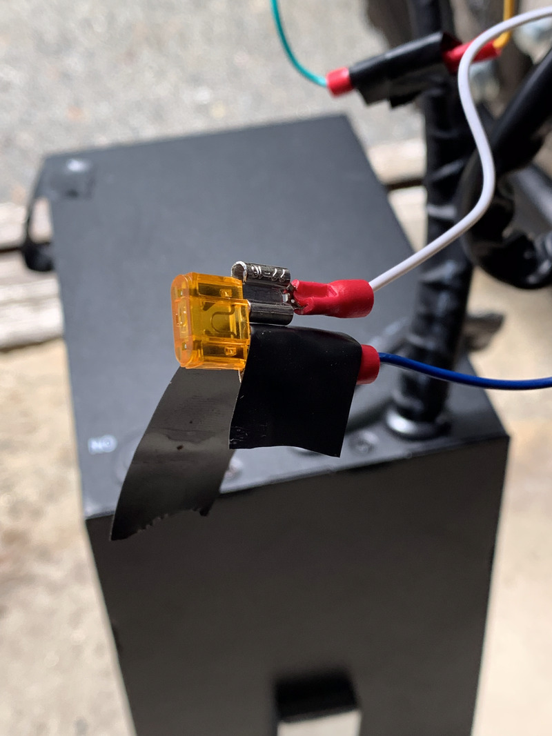
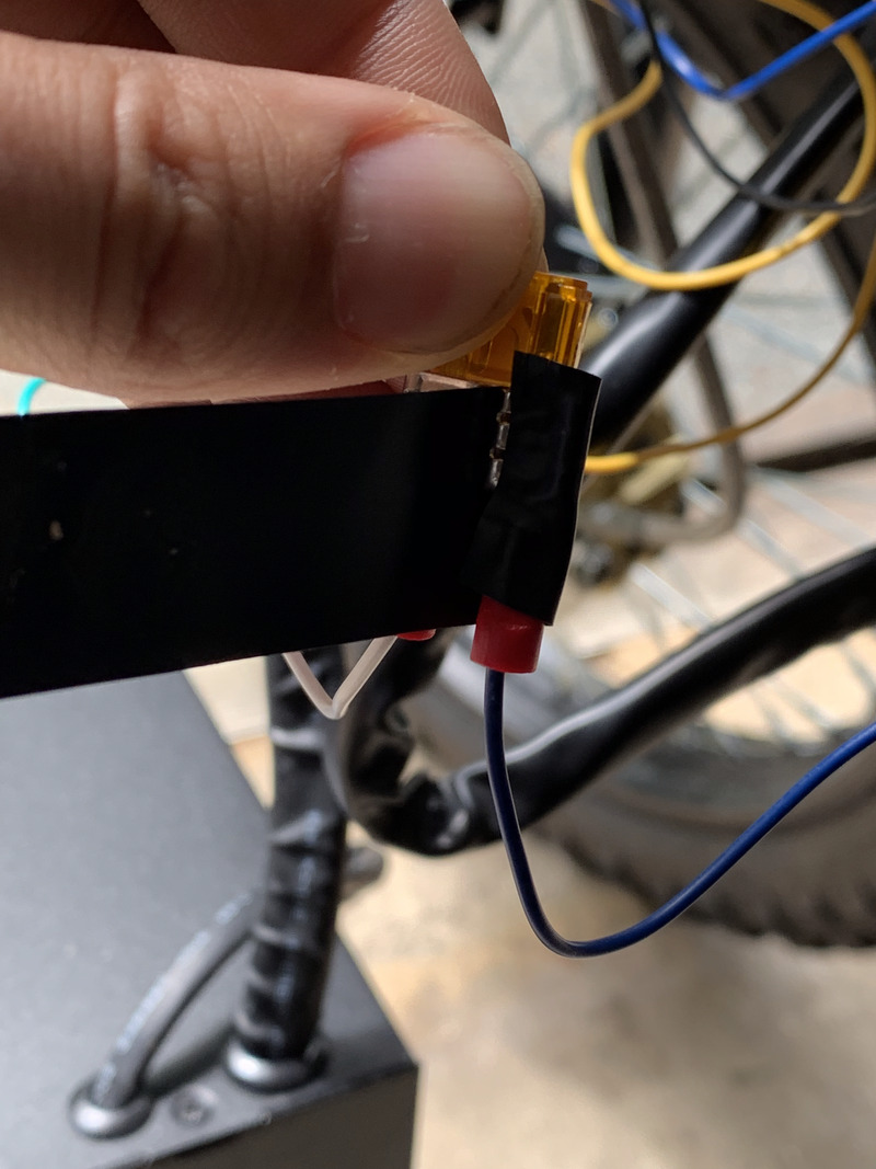
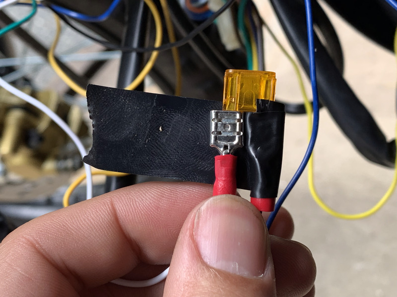
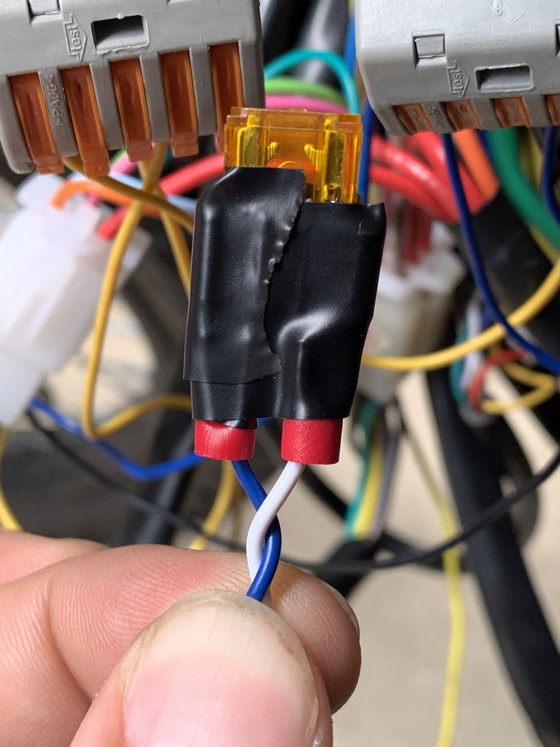
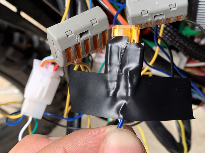
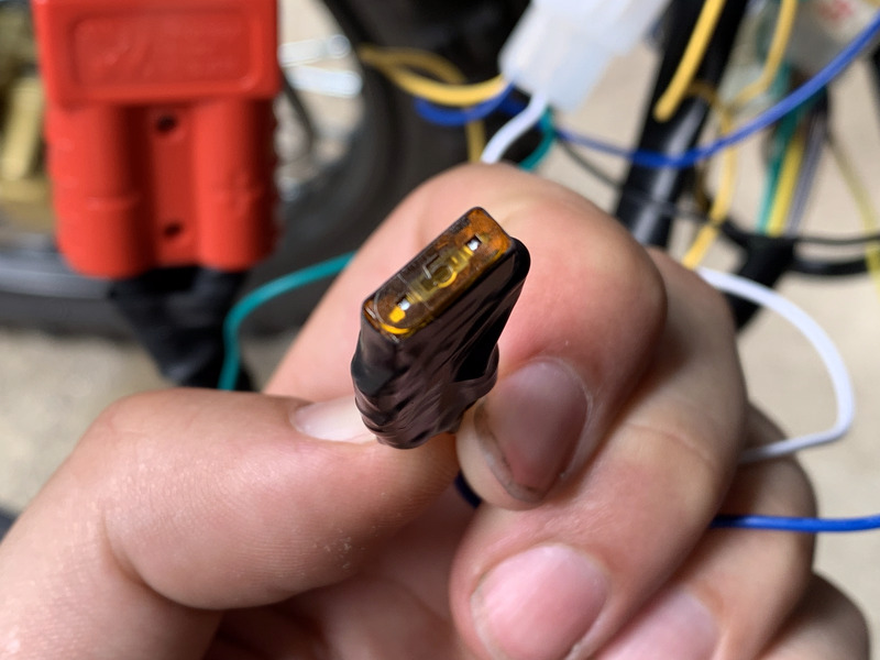
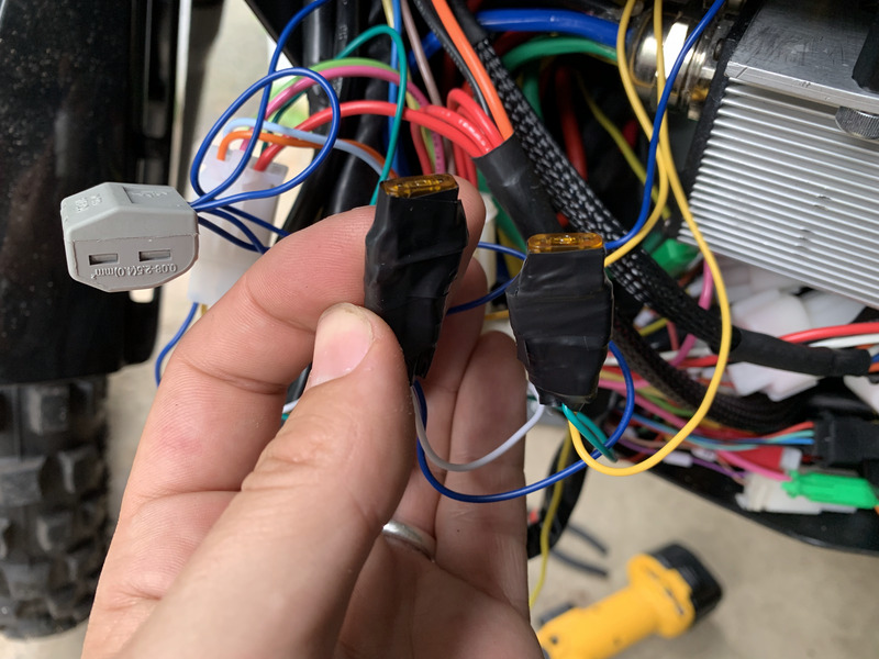
Repeat the above, using a yellow wire instead of a blue one, and connect it to the green wire from the harness instead of the white one. You now have both your fuse assemblies complete:
Run Wires to Your Blinkers
Front Blinkers
Cut 1’ of yellow wire, 1’ of blue wire, 1’ of black wire, and 3” of black wire.
Crimp the red wire from the right front blinker to the yellow wire.
Crimp the red wire from the left front blinker to the blue wire.
Crimp both the 1’ and the 3” black wires to the black wire from the left front blinker.
Crimp the other end of the 3” black wire to the black wire from the right front blinker.
Cover all crimped connections with enough electrical tape to make them water tight.
You now have 1’ wires of yellow, blue, and black. Run them into the enclosed compartment, and down below the battery.
Turn the front wheel fully from side to side, making sure you aren’t pinching or pulling on the wires. Adjust as needed.
Rear Blinkers
Cut 3’ of yellow wire, 3’ of blue wire, 3’ of black wire, and 3” of black wire.
Connect things just as you did for the front blinkers, using yellow for the rear right blinker, blue for the rear left blinker, and black for the grounds of both rear blinkers. Seal connections with electrical tape.
Gently remove the excess brake light wiring from the tube frame that runs from the back of the bike to the main compartment.
Thread your 3’ yellow, blue, and black wires down the tube and into the compartment. It may help to tape them all together so that they come through as one unit rather than three distinct wires.
Place the excess brake lighting back into the tube frame assembly.
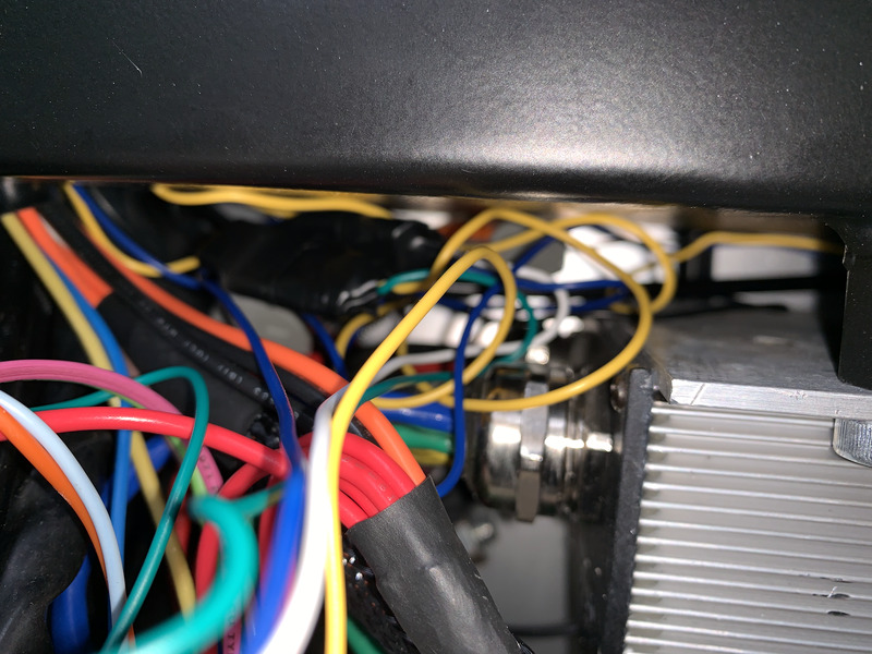
Run your three wires into the enclosure.
Route your wires along the top of the enclosure, above the DC-DC converter and controller, toward the ones from the front.
Connect It!
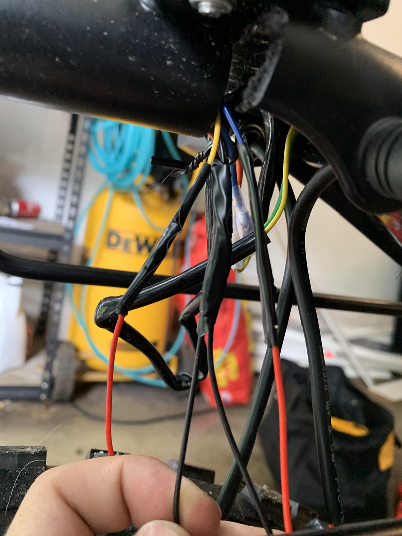
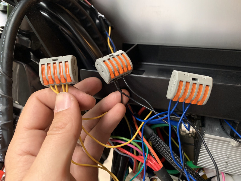
It may seem like you have an overwhelming jumble of wires at this point, but the rest is actually very easy. All you need to do is connect all wires of like colors together using lever nuts.
First, connect the four yellow wires (front blinker, rear blinker, harness, fuse assembly).
Next, connect the four blue wires (ditto).
Finally, connect the three black wires (front blinker, rear blinker, ground screw).
At this point, everything should work. I recommend connecting the battery, turning the bike on, and testing your new blinkers. If things work, great! Disconnect the battery and proceed. If not, retrace your steps and fix any mistakes.
Put Everything Back Together
Push all of your wiring – fuses, lever nuts, harness up into the free space at the top of the bottom compartment. Push all other wires back into the compartment.
Replace the aluminum sides, being careful not to pinch any wires, as well as not to strip any threads.
Plug in your battery, power on your bike, go for a ride, and show other drivers where you’re going!
Ackwnowledgments
Huge thanks to:
- Josh Kendrick, for documenting his findings about the RCR’s wiring harness, and for pointing me to the blinkers used in this post.
- Tim Seward, for providing me with the Onyx wiring diagrams (and yeah, for founding Onyx).